H 264 Dvr Circuit Diagram
Reset password for dahua dvr/nvr Dvr 264 recorder 8ch cameras channel camera Schematic diagram of dvr
H-264-DVR-8CH-StandAlone-DVR.jpg
H.264 decoder block diagram Diagram circuit wiring dvr h264 camera kb jpeg security Wiring satellite coax xplod
H264 dvr circuit diagram
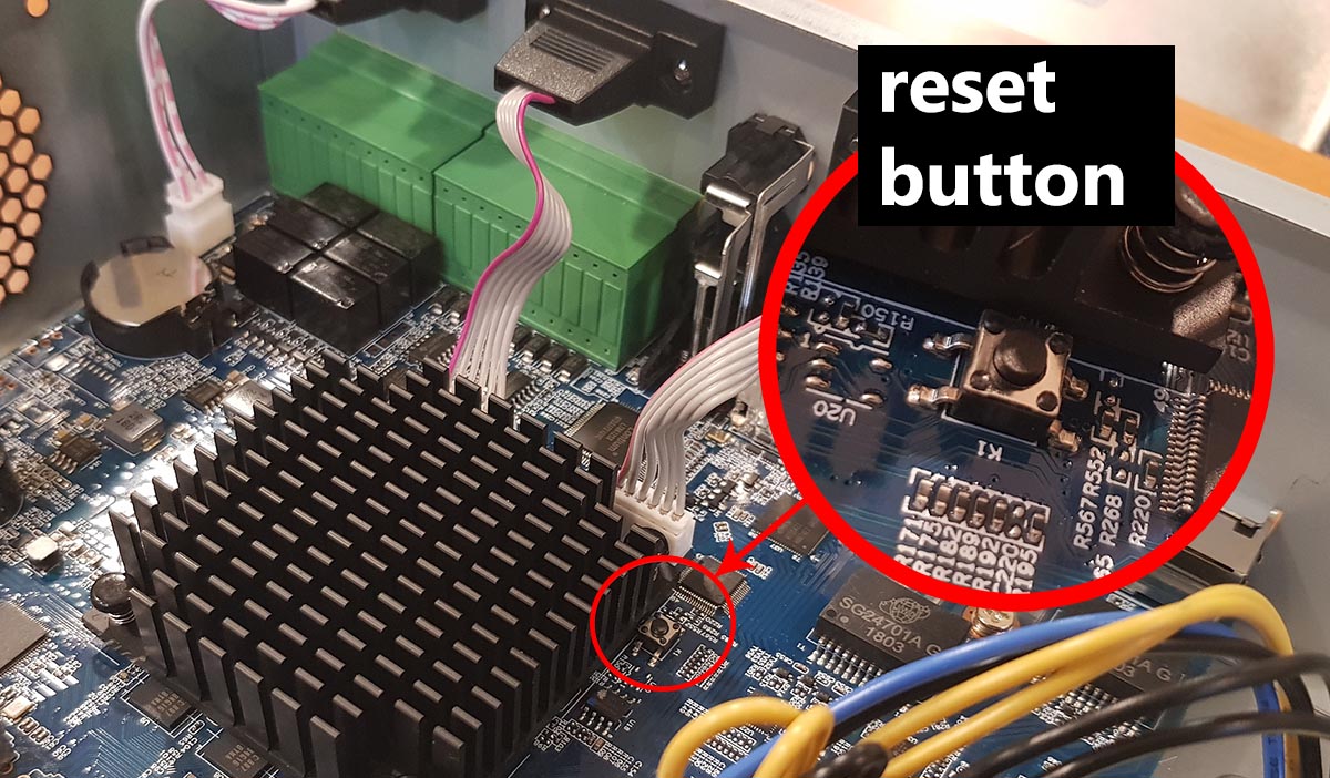
Circuit board #gm8182t no name h.264 dvrReset dvr avtech resetear cctv nvr h264 clave avc Dvr swells restorer blockDvr 264 reset board firmware factory cctvforum circuit name digital general hardware default menu 8ch h264 cctv through purchased v01.
Dvr reset nvr dahua jumper forgotpasswordHow to reset h.264 dvr nvr (forgotpassword) Typical dvr circuit topology (single-phase representation) fig. 3 showsDahua nvr dvr motherboard located.
![30 Schematic Diagram of a DVR "Source: [26]" | Download Scientific Diagram](https://i2.wp.com/www.researchgate.net/profile/Aushiq-Ali-Memon/publication/281442123/figure/download/fig20/AS:646103267561472@1531054431290/Schematic-Diagram-of-a-DVR-Source-26.png)
H-264-dvr-8ch-standalone-dvr.jpg
Decoder h26430 schematic diagram of a dvr "source: [26]" H264 dvr circuit diagramHow to reset h.264 network dvr.
.


